Language


More Language
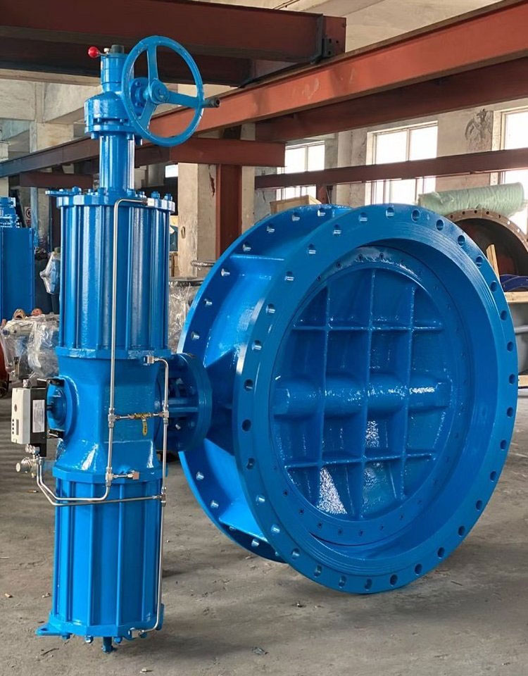
Language Large-diameter butterfly valves (DN ≥ 300 mm) are critical fluid control components widely applied in water supply and drainage, petrochemical, power generation, metallurgical, and HVAC systems.
Large-diameter butterfly valves (DN ≥ 300 mm) are critical fluid control components widely applied in water supply and drainage, petrochemical, power generation, metallurgical, and HVAC systems. Characterized by low pressure loss, wide rangeability, and high precision, their operational reliability, service life, and system safety are directly determined by proper installation environment selection and standardized maintenance practices. This comprehensive guide details professional requirements for the installation environment and maintenance of large-diameter butterfly valves, helping engineers, facility managers, and maintenance technicians implement scientific operation and management, while optimizing for Google SEO to ensure better visibility and relevance.
1. Installation Environment Requirements for Large-Diameter Butterfly Valves
The installation environment of large-diameter butterfly valves is constrained by spatial conditions, pipeline matching, medium characteristics, and load-bearing safety. Non-compliant installation environments are the primary cause of early valve failures, such as sealing surface damage, valve plate jamming, and actuator malfunction. Below are the professional requirements to ensure optimal performance.
1.1 Spatial and Positioning Requirements
• Indoor Priority with Outdoor Protection: Indoor installation is recommended to avoid direct exposure to harsh weather conditions. For outdoor installations, the valve and its actuator must be equipped with sun-proof, rain-proof, corrosion-proof, and lightning protection measures. The actuator’s protection level shall not be lower than IP67 to resist dust, rain, and corrosive gas erosion, ensuring long-term stable operation. Additionally, valves stored outdoors for extended periods should have their internal heaters powered to prevent condensation in the control unit.
• Maintenance-Friendly Layout: The installation position must reserve sufficient operating space (≥ 1.5 times the valve diameter) for maintenance tools and personnel. Avoid areas with strong electromagnetic interference, high-temperature radiation, or corrosive gas accumulation, as these can cause actuator signal distortion and component damage. The installation site should also be easily accessible for regular inspections and repairs.
• Pipeline Coaxiality and Alignment: The valve shall be installed horizontally (pipe inclination ≤ 5°), with the valve stem perpendicular to the medium flow direction. The pipeline and valve body must be strictly coaxial; any offset will cause uneven stress on the sealing surface, leading to early leakage and valve plate jamming. Never use the valve’s bolts to pull misaligned pipes into position—always adjust the piping system first.
• Load-Bearing Safety: Large-diameter butterfly valves have significant weight (e.g., a DN3000 valve can exceed 5 tons). Dedicated pipe supports must be installed to bear the valve’s dead weight; the pipeline shall not be used to support the valve. Lifting must be done using the valve body’s dedicated lugs—never use the handwheel, valve stem, or actuator as lifting points, as this can cause structural deformation and damage.
1.2 Pipeline and Flange Matching Conditions
• Straight Pipe Section Requirements: To ensure a stable flow field and avoid turbulence that affects sealing performance, the straight pipe section upstream of the valve shall be ≥ 10 times the pipe diameter (D), and a minimum of 20D is recommended for optimal performance. The downstream straight pipe section shall be ≥ 5D to maintain flow stability after the valve. Avoid installing the valve too close to pipe elbows, tees, or other fittings, as this may restrict disc movement and damage the seat.
• Flange and Gasket Specifications: The pipeline flange shall be flat, coaxial, and clean, free of burrs, rust, or foreign matter. The flange spacing must match the valve body’s thickness, and high-strength bolts should be used for connection. Tighten bolts in a cross-pattern sequence and avoid over-torquing, especially for resilient-seated valves, to prevent flange deformation or sealing failure. The flange gasket shall not protrude into the pipeline, as this can interfere with flow measurement and valve operation.
• Pre-Installation Pipeline Cleaning: Before installation, thoroughly clean the pipeline to remove welding slag, iron filings, sediment, and other impurities. For media containing solid particles, install a filter with a precision of 5 μm upstream to prevent foreign matter from entering the valve cavity, which can cause sealing surface wear and valve plate jamming. It is recommended to use a straight pipe or bypass pipe to flush the pipeline before installing the valve, and never weld with the valve in place.
1.3 Medium and Working Condition Adaptation
• Temperature and Pressure Limits: Soft-sealed butterfly valves (using EPDM/PTFE seals) are suitable for media temperatures ≤ 120℃ and working pressures ≤ 1.6 MPa. Hard-sealed butterfly valves (metal-to-metal seals) can withstand temperatures up to 425℃ and pressures ≤ 6.4 MPa. Exceeding these limits will lead to seal degradation, metal fatigue, and premature failure. Never use the valve for line testing at pressures higher than the nameplate rating, as this can cause leakage and damage.
• Medium Compatibility: For corrosive, high-viscosity, or abrasive media, the valve body, valve plate, and sealing parts should be made of corrosion-resistant (e.g., 316L stainless steel, PTFE lining) or wear-resistant materials (e.g., hard surfacing alloy). For media containing suspended solids, consider using an eccentric plug valve instead of a standard butterfly valve for better performance. A thermal expansion gap of 0.5–1 mm should be reserved for high-temperature media to prevent valve stem jamming caused by thermal expansion.
• Installation Posture: During installation, keep the valve plate slightly open (4–5°) to avoid excessive compression of the sealing surface, which can cause permanent deformation of soft seals. Never install the valve in a fully closed state, as this can damage the seal edge and make bolt hole alignment difficult.
2. Professional Maintenance Precautions for Large-Diameter Butterfly Valves
Large-diameter butterfly valves have long service cycles but require regular, standardized maintenance to maintain performance. Maintenance should follow a hierarchical approach: daily inspection → regular maintenance → shutdown maintenance, with a focus on sealing performance, actuator operation, and mechanical structure integrity. Proper maintenance can extend the valve’s service life by 30–50% and reduce unplanned downtime.
2.1 Daily Inspection (Weekly/Monthly)
• Leakage Detection: Regularly check the flange connection, packing gland, and valve body sealing surface for medium leakage. For soft-sealed valves, focus on seal edge leakage; for hard-sealed valves, check for abnormal noise and slight leakage during full closure. Promptly address any leakage to prevent further damage to the valve and pipeline system.
• Operation Smoothness Check: Perform manual and automatic opening/closing operations to confirm that the valve plate moves smoothly without jamming, abnormal noise, or position deviation. Never leave the valve in a partially open state (15°–75°) for long periods, as this will cause severe erosion of the sealing surface, valve plate vibration, and bearing wear.
• Actuator Status Inspection: For pneumatic actuators, check air source pressure, pipeline leakage, and filter element cleanliness. Ensure the air source pressure meets the actuator’s rated value (usually 0.4–0.6 MPa). For electric actuators, test motor insulation, limit switch accuracy, and signal transmission stability. Verify that the manual-automatic switching function is normal to ensure emergency operation capability.
2.2 Regular Maintenance (Every 6 Months; Every 3 Months for Severe Working Conditions)
• Cavity and Sealing Surface Cleaning: Drain the medium in the valve cavity, remove residual impurities, and clean the sealing surface with a soft cloth (avoid hard tools to prevent scratches). For media containing oil or scale, use a special cleaning agent for degreasing and descaling. Reinstall flange covers after cleaning to prevent dust and moisture accumulation.
• Lubrication Management: Apply special grease (high-temperature resistant grease for high-temperature working conditions) to the valve stem, bearing, and actuator moving parts. Ensure sufficient lubrication while avoiding excessive grease injection, which can cause packing jamming. For resilient-seated valves, coat the rubber surfaces of the disc with a thin film of FDA-approved grease to prevent aging.
• Sealing Performance Maintenance: For soft-sealed valves, inspect the seal for aging, deformation, or damage; replace the seal immediately if defects are found. For hard-sealed valves, check for wear and scratches on the sealing surface—minor defects can be repaired by grinding, while severe damage requires replacement of the sealing pair. Regularly check the valve seat for adjustability and replaceability as needed.
• Packing and Fastener Maintenance: If packing leakage occurs, tighten the gland evenly; if leakage persists, replace the packing (adjacent packing rings should be staggered by 90°–120° to improve sealing effect). Inspect flange bolts and actuator fasteners for looseness or corrosion, and tighten or replace them as needed. Avoid using bolts of incorrect specifications, as this can damage the valve or prevent proper closure.
• Actuator Overhaul: Disassemble and clean the pneumatic cylinder, replace worn parts and seals. For electric actuators, test motor current, torque, and limit switch accuracy, and calibrate control parameters according to system requirements. For actuators with positioning devices (e.g., SAMSON positioners), check for feedback fluctuations and adjust parameters to avoid resonance.
2.3 Shutdown Maintenance for Long-Term Inactivity
• For valves inactive for ≥ 3 months, keep the valve plate slightly open and completely drain the valve cavity to prevent medium corrosion and seal adhesion. Clean the internal residual liquid and adherents thoroughly, and seal the power interface to prevent moisture intrusion.
• Apply anti-corrosion and dust-proof coatings to exposed valve stems, actuators, and fasteners. Cover the valve with a protective cover to avoid dust and moisture accumulation. For long-term storage (≥ 6 months), indoor storage is recommended, and the valve should remain in its original packaging if possible.
• Perform full opening and closing operations 2–3 times per quarter to keep moving parts flexible and prevent seal bonding and valve stem jamming. This helps maintain the valve’s operational readiness for future use.
2.4 Fault Handling Principles
• Leakage Fault: First, check for flange loosening and foreign matter accumulation; tighten the flange or clean the foreign matter. For persistent leakage, shut down the system, replace the sealing parts, or repair the sealing surface. Common causes of leakage include worn gaskets, loose bolts, and damaged seals.
• Jamming Fault: Never force the valve to operate if jamming occurs. Check for foreign matter in the valve cavity, sealing surface damage, packing over-tightening, or actuator malfunction. Remove foreign matter, adjust packing torque, or repair the actuator. Common causes of jamming include valve stem rust, scale buildup, and improper alignment.
• Actuator Fault: Switch to manual operation first to ensure system safety, then troubleshoot the air source, circuit, motor, or limit switch. For pneumatic actuators, check for insufficient air pressure or cylinder seal leakage; for electric actuators, inspect the motor and wiring. Do not disassemble the actuator without professional training to avoid misalignment of internal components.
3. Key Prohibited Operations (Avoid Common Mistakes)
• Forced installation with misaligned flanges (the main cause of 90% of early valve failures).
• Single-side or excessive tightening of flange bolts, leading to valve body deformation and valve plate jamming.
• Rapid opening and closing of the valve, which can cause water hammer and gas corrosion damage to the sealing surface.
• Operation beyond the rated temperature, pressure, and medium range, resulting in seal failure and mechanical component damage.
• Using the valve as a lever or support point during installation, which can deform the valve stem and render the valve useless.
• Disassembling and maintaining the valve without following the manufacturer’s technical specifications, leading to component mismatch and performance degradation.
4. Conclusion
The installation and maintenance of large-diameter butterfly valves require strict adherence to professional standards and best practices. Scientific environmental selection, precise installation operations, and standardized maintenance management not only ensure the stable operation of the valve itself but also improve the safety and efficiency of the entire fluid pipeline system. Engineering personnel should combine on-site working conditions and the manufacturer’s technical documents to formulate personalized maintenance plans, realizing the full-life-cycle management of the valve. By following the guidelines outlined in this article, you can minimize valve failures, reduce maintenance costs, and extend the service life of large-diameter butterfly valves.
FAQs (Google SEO-Friendly)
Q1: What is the minimum straight pipe section requirement for large-diameter butterfly valves?
A1: The upstream straight pipe section should be ≥ 10D (recommended 20D), and the downstream straight pipe section should be ≥ 5D to ensure stable flow and optimal valve performance.
Q2: How often should large-diameter butterfly valves be maintained?
A2: Regular maintenance is recommended every 6 months under normal working conditions; for severe working conditions (corrosive, abrasive media), maintenance should be performed every 3 months.
Q3: What is the protection level requirement for outdoor-installed large-diameter butterfly valve actuators?
A3: The actuator’s protection level shall not be lower than IP67 to resist dust, rain, and corrosive gas erosion.
Q4: Why should large-diameter butterfly valves not be left partially open for a long time?
A4: Long-term partial opening (15°–75°) causes severe erosion of the sealing surface, valve plate vibration, and bearing wear, leading to premature valve failure.
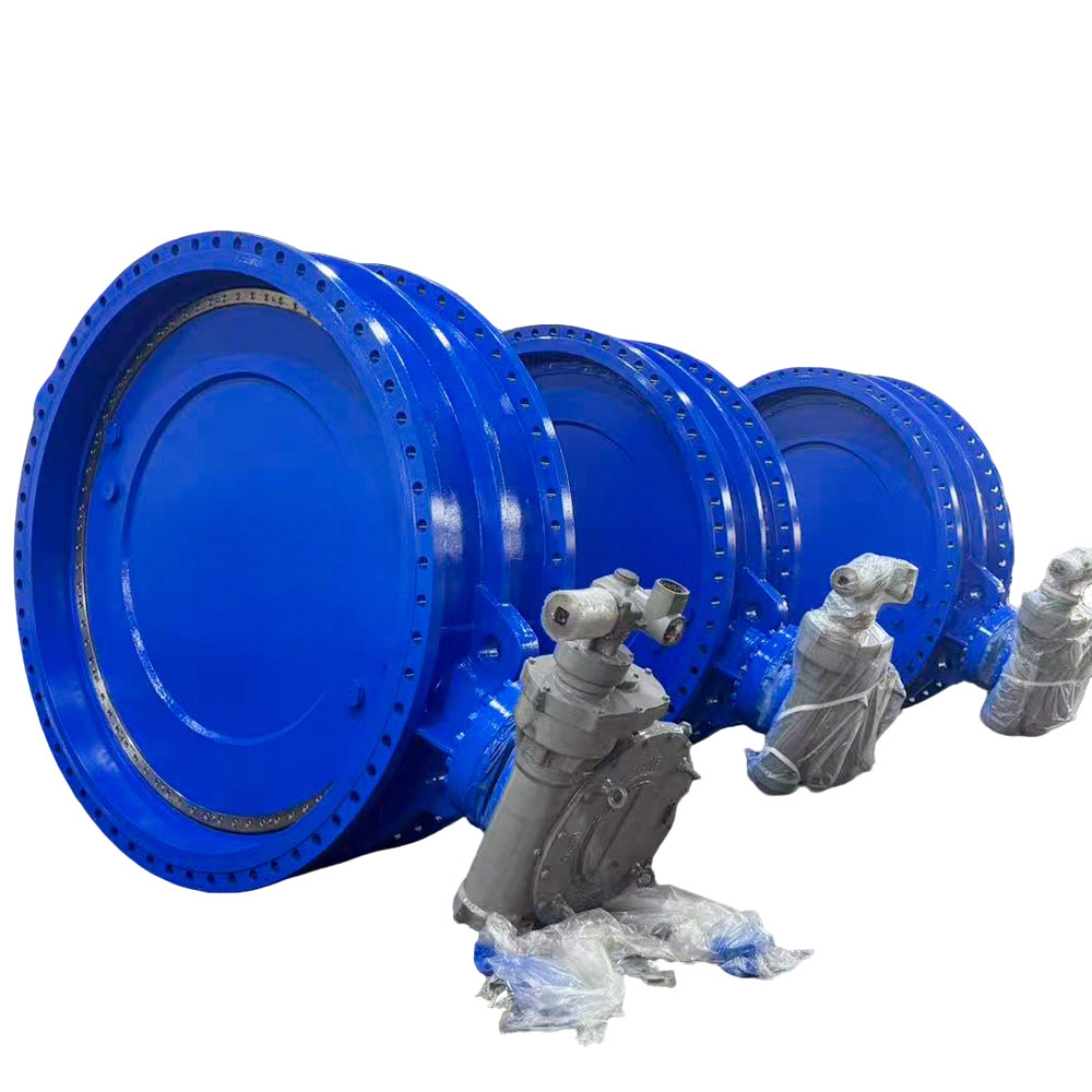
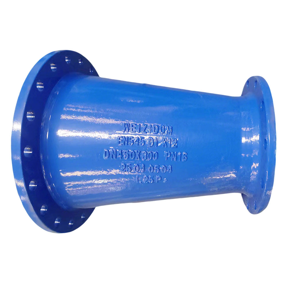
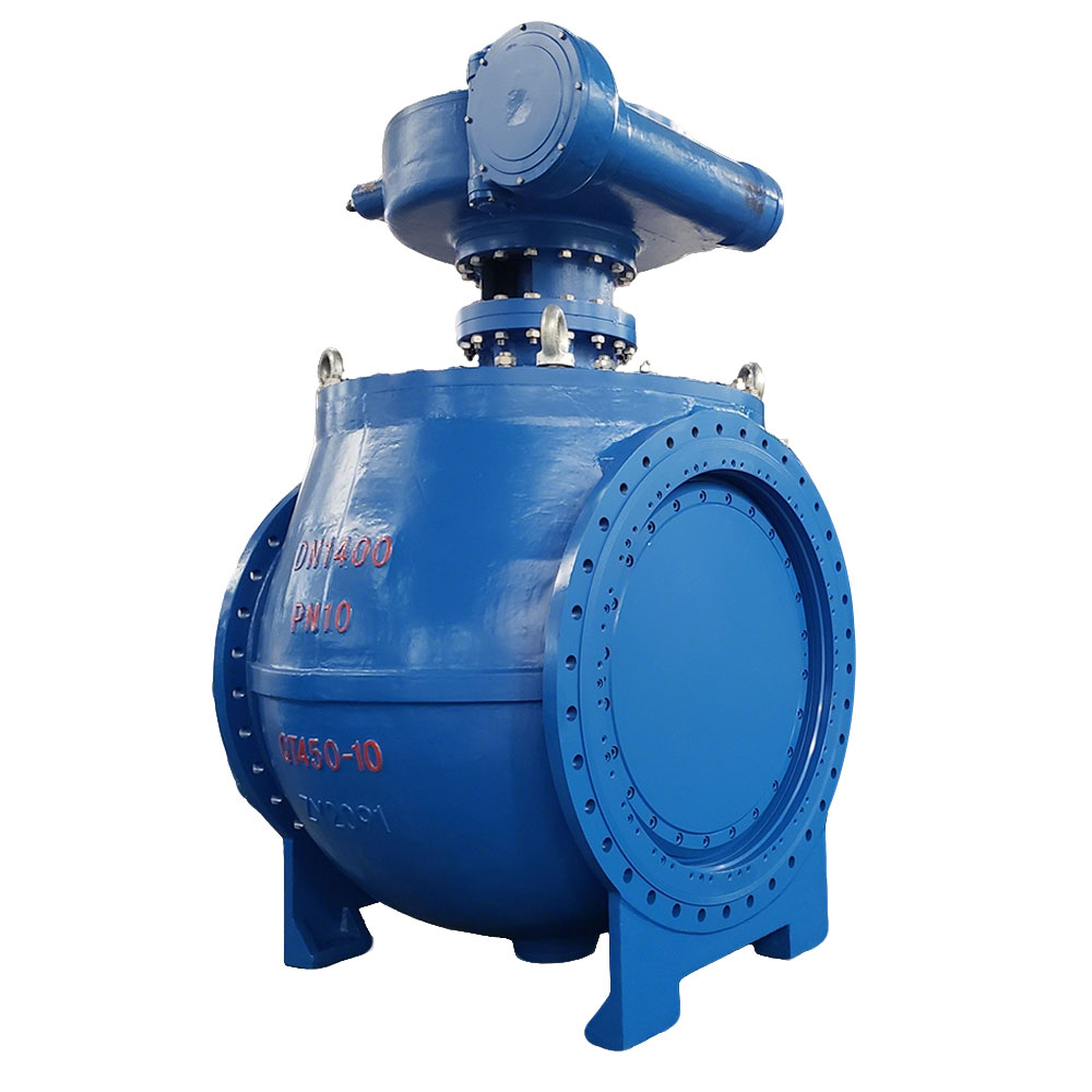
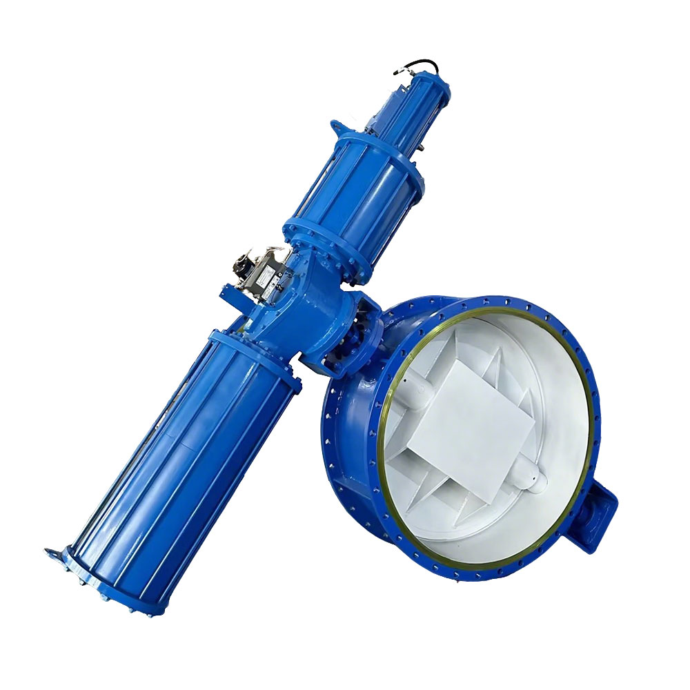
Various Models for Your Choice

Have be any question? Feel free to Contact.


WEIZIDOM Group is specializes in the manufacturing, sale and after-sale service of valves, pipe fittings, water meters, flow meters and other pipeline accessories.
Copyright © 2026.WEIZIDOM All rights reserved.